
Pulse-Width Modulation (PWM) - Theory
Pulse-Width Modulation (PWM) is an effective method of using digital signals to control analog circuits like dimming an LED or controlling motor speeds.
Pulse-Width Modulation (PWM) series of articles:
- Read Pulse-Width Modulation (PWM) - Theory to understand the theory behind
- Build a simple circuit with RPIO using Hardware-based PWM with RPIO
- Build a simple circuit using PIGPIO using DMA-based PWM with PIGPIO
We have seen in the Hello IoT (RPIO) and Hello IoT (PIGPIO) articles how Raspberry Pi can put 3.3 volts (logic HIGH) on GPIO18 and the LED turns ON, or 0 volts (logic LOW) and the LED turns OFF. But can we dim the LED? Great question! I am glad you asked. Before I can answer that, we need to discuss few things.
How to dim an LED?
Let’s look at a simple datasheet for a standard LED. While this datasheet may not be the one for the LED we are using, all of them have similar behaviour. Some of the values may be a bit different but the concepts, which is what I want to show you, work the same way.
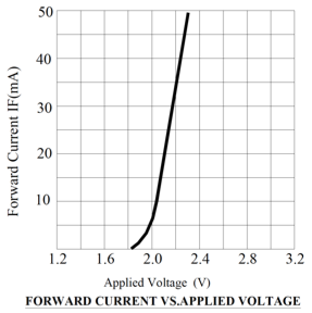
There are two specific charts that I want to highlight from that datasheet. The first chart shows the forward-current and forward-voltage operations. What is interesting to see here is that the voltage is around 2.2 volts (1.8 volts to 2.4 volts). It does not change much. But the current goes from 0 mA to 50 mA!
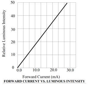
Therefore, we can imagine that current is probably more important than voltage when changing the intensity of the LED because it has a more significant variation. The second chart from the same datasheet confirms this relationship, illustrating that the intensity is directly proportional to the current flowing through the LED.
“Fantastic, we can dim the LED by varying the current! But how?”
We can build a simple circuit with a Potentiometer, an LED, and a battery, as shown below:
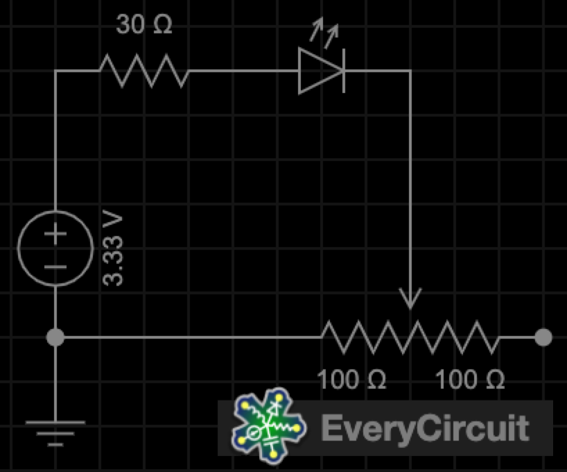
The 30 Ω resistor protects the LED when the potentiometer is set to 0 Ω. By varying the potentiometer from 0% (0 Ω) to 100% (200 Ω) we can vary the current and therefore dimming the LED. I used a very cool simulator named EveryCircuit to see the different values for the voltages, current and intensity of the LED. This is shown on this animation:
The previous animation is cool, but Raspberry Pi doesn’t have hands to change the value of a potentiometer!
You are right. The code we have seen in the previous articles does not even change the current; it only outputs a voltage (HIGH or LOW). Let’s see how we could control the current.
Power
Wait, I thought you were building a story to modify the current, and now you are switching to talk about power? What is going on?
Don’t worry. I promise it is going to make sense soon. Let’s go back and cover some basic concepts. Do you remember the definitions for voltage, current and resistance?
Wikipedia defines these terms like this: the voltage (volts) is how much energy is between two points on a circuit. The current: (amperes) is how fast the charge is flowing through a circuit. The resistance: (ohms) is how much the circuit resists the flow of charge.
I have seen a great cartoon that visually explains the relationship between these terms.

These terms are so important that we have the Ohm’s law. This law states that in “an electrical circuit, the current passing through a resistor is related to the voltage difference and the electrical resistance between the two sides, as long as the physical conditions and the temperature of the conductor remain constant.”
Voltage = Current * Resistance
In the circuit above, the minimum resistance is 30 Ω. We do not have zero ohms resistance unless we have a short circuit, and we probably do not want that. So, as long as we have voltage, we must have current. If we do not have voltage, we do not have current, and vice-versa.
The relation between current and voltage is so essential to a circuit that we even have a word to define it: power!
Power, measured in Watts, is defined as the amount of energy transferred or converted per unit of time. We have another important formula to calculate the value:
Power = Voltage * Current
The table below shows the values for voltage, current, resistance and power in the circuit we had seen earlier as we vary the resistance in the potentiometer
| Percentage | Resistance (Ω) | Voltage (V) | Current (mA) | Power (mW) |
|---|---|---|---|---|
| 1% | 32 | 2.07 | 39.30 | 81 |
| 10% | 50 | 2.03 | 26.00 | 53 |
| 20% | 70 | 2.00 | 19.10 | 38 |
| 30% | 90 | 1.97 | 15.10 | 30 |
| 40% | 110 | 1.95 | 12.50 | 24 |
| 50% | 130 | 1.94 | 10.70 | 21 |
| 60% | 150 | 1.92 | 9.39 | 18 |
| 70% | 170 | 1.91 | 8.36 | 16 |
| 80% | 190 | 1.89 | 7.54 | 14 |
| 90% | 210 | 1.88 | 6.87 | 13 |
| 99% | 228 | 1.88 | 6.36 | 12 |
I think I am following you, but I am still confused. How is the Raspberry Pi going to dim the LED? We can’t use a potentiometer unless we had a motor, and that would be complicated.
Ok, let’s talk about that.
- We can’t change the resistance of the circuit because we would have to change the circuit or change the potentiometer manually or with a motor, and that would be cheating.
- We can’t change the voltage on the GPIO pin; it’s either 3.3 volts or zero volts but not a value in between. Also, voltage changes do not affect the intensity of the LED, so that would not help much.
- The ohms law tells us that we have a fixed current if we have a fixed voltage and a fixed resistance.
It looks like we are stuck!
Fortunately, looks are deceiving!
Remember, power is the amount of energy transferred or converted per unit of time. It’s about the number of electrons that are flowing through a circuit per second.
How is that going to help us?
Because we can use an average value for the power, and we do not have to send all the electrons at a constant speed! Check out the animation below.
The Raspberry Pi outputs 3.3 volts at about a constant current (see note below) but for specific amounts of time, rather than doing that all the time. You can see the average power (purple line) increases as the duty cycle increases, and it decreases when the duty cycle decreases. So, if we can control the duty cycle, we control the average power for our circuit, and therefore we dim the LED.
Notes:
- The current output from the Raspberry Pi is constant because the resistance of the circuit is constant.
- Period is the total time for each set of HIGH levels and LOW levels. We usually fix the value of the period.
- The frequency is the reciprocal of the period.
- The Pulse Width is the time of HIGH-level outputs.
- The duty cycle is nothing else than the percentage of time a digital signal is HIGH over an interval or period.
- PWM is not an analog signal, but the average power is equivalent to the corresponding analog value, especially if the frequency is high.
In this article, we discuss the Pulse-Width Modulation (PWM) theory to understand why PWM works. In the following articles, we will learn how we can get PWM working on Raspberry Pi using JavaScript. I am going to show you two versions of the same project, one written using RPIO and one using PIGPIO.
Why am I using both libraries? Great question! I am glad you asked. For things like PWM, the two libraries work very differently. RPIO uses hardware-based PWM, but PIGPIO uses DMA-based PWM.
Which one is better? That’s another excellent question.
Hardware-based PWM does not require CPU resources, and it has a more precise time control. Even if the CPU is busy, the Raspberry Pi updates the correct values at the correct time. But on the Raspberry Pi 4, we only have four pins that we can use: GPIO18 (pin 12), GPIO12 (pin 32), GPIO13 (pin 33), and GPIO19 (pin 35). Suppose we were building a circuit with an RGB LED (which requires 3 PWM pins - one for each colour) and one switch; we would run out of pins!
UPDATE Bogusław Kempny has indicated, on a comment for another article, that the Raspberry Pi only has 2 channels. Pins GPIO12 (pin 32) and GPIO18 (pin 12) share channel 0, and pins GPIO13 (pin 33) and GPIO19 (pin 35) share channel 1. This means we would not be able to use an RGB led!
Software-based PWM, on the other hand, uses the CPU to continuously put either a HIGH or LOW value on the output pin, depending on the state in the duty cycle, but we can use any GPIO pin.
I’m not too fond of either of these extremes, and I wish there were a better way. Wish granted! You can use DMA-based PWM. So what is that? I’m glad you asked.
DMA-based PWM is the best of both worlds. It’s similar to hardware-based PWM as far as efficiency goes, but it works like software-based PWM because you can use and GPIO pin. The DMA (Direct Memory Access) controller is part of the Raspberry Pi’s chip (Broadcom). It can’t run code (like the chip does), but it can copy memory across peripherals by itself without consuming the central processor’s time. The DMA controller has different channels which can copy memory, and it runs independently of the CPU. Providing PWM via DMA frees the CPU, allowing low processor usage to drive DC motors, servos, LEDs, or any other analog device using the GPIO pins. Raspberry Pi allows you to control a total of 10 individual channels, not just 2 like hardware-based PWM.
Support me with a small contribution by Paypal or, if you prefer, buy me a coffee.
Please leave a comment
Comments are powered by Utterances. A GitHub account is required to comment. Comments are moderated. Be respectful. No swearing or inflammatory language. No spam.
I reserve the right to delete any inappropriate comments. All comments for all pages can be viewed and searched online here.
Opinions expressed in this blog are solely my own and do not express the views or opinions of my employer, wife, son, friends, boss, or anybody else! 😀
To edit or delete your comment: