
Analog To Digital Conversion (I2C) with PIGPIO
The second part of the I2C series implements a ADC with I2C using PIGPIO library
PIGPIO npm library does not implement I2C, but the same author Brian Cooke (fivdi) has given us a nice package to work with I2C named i2c-bus.
This article is a continuation of an article named “Analog To Digital Conversion (I2C) with RPIO” that I wrote a couple of weeks ago. Please make sure you read that to better understand this project. At least make sure you read these sections:
- Digital Vs. Analog Signals
- Analog-to-Digital Conversion
- Voltage Divider
- Configure Raspberry Pi
- ADS7830
- Address
- Channels
I am going to assume you have read it and only discuss the differences here.
Project
We are going to build this simple circuit.
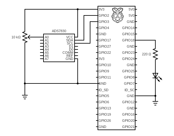
The potentiometer is going to work as a voltage divider. As we change the resistance value, the voltage detected on pin A0 of the ADS7830 ADC chip changes. The chip converts the voltages to values from 0 (representing 0 volts) to 255 (representing 3.3 volts), and the Raspberry Pi receives this value on the SDA (GPIO2) pin. Our code takes that value, displays it on the console and sends it to the class that controls the LED, which we discussed in this article DMA-based PWM with PIGPIO.
Code
1Import the i2c-bus npm library2Import the PIGPIO library.3Define a constant Gpio to reference the Gpio class in the Pigpio library.4Import the pins library. See the article GPIO Pins to understand why this is required.6-33This is the class that we created to use the ADC chip. Make sure you have read Analog To Digital Conversion (I2C) with RPIO to understand how I got to these numbers.7We are holding an instance of the I2C so that we can call different functions.8The ADDRESS where we can find the I2C chip. See Analog To Digital Conversion (I2C) with RPIO to understand how we got to this value9The CHANNELS is an array of values, one for each channel. See Analog To Digital Conversion (I2C) with RPIO to understand how we got to these values11-15Contructor to initialize the I2C via a promise (asynchronously)12UsesopenPromisifiedto open the bus asynchronously.- The first parameter busNumber is the number of the I2C bus/adapter to open. You can provide these values: 0 for /dev/i2c-0, 1 for /dev/i2c-1, …
- The
/dev/i2c-0is not available on the Raspberry Pi 3, and I assume that holds for later versions of the Raspberry Pi./dev/i2c-0is used by the GPU firmware side to talk to a GPIO expander, as well as HAT EEPROMs, the camera, and display. Accessing the I2C peripheral from ARM and GPU causes issues. Read more about this here
17-28This function reads the values from the chip.18Let’s initialize the value to a -1. If the I2C bus is not ready, the function returns this value.19-26Skip reading the value if the I2C bus is not ready. Remember, opening the bus connection is asynchronous.20Node.js documentation explains that this function allocates a new Buffer using an array of bytes up to 255 characters long. The value we are putting here is the command byte we in the Analog To Digital Conversion (I2C) with RPIO article. Note that this expects an array of bytes! That’s why we have to put the value inside square brackets.21Node.js documentation explains that this function allocates a new Buffer of size (defined by the parameter) bytes. If fill is undefined, which in our case it is, Node.js fills the buffer with zeros. But this does not matter because we are using that array to get the digital conversion, overriding the value.23We are writing Asynchronously to the I2C bus the buffer that contains the value of 0x84, which is the command byte to request the ADS7830 to convert the analog value on channel 0.24We are reading from the I2C bus into the one-byte buffer.- The output from the read gets stored in a variable named
datacontaining 2 properties:bytesReadindicates how many bytes to expect, andbufferholds a buffer with the data.
- The output from the read gets stored in a variable named
25We convert the data structure returned into a number field using the readUIntBE which “ReadsbytesReadnumber of bytes frombufferat the specified offset (0 in our case) and interprets the result as an unsigned big-endian integer supporting up to 48 bits of accuracy.”27We return the value read, or -1 if the I2C bus is not ready30-32Shutting down the application calls this function.31Close the I2C bus35-61This class is the same we had discussed in the DMA-based PWM with PIGPIO article. The only difference is on lines57-59where we only want to close PIGPIO if this is the last usage.63-96This is the main class for our project. It’s responsible for reading the value from the ADS7830 ADC chip and providing that value to the LED so that it can be dimmed. This code is the same as we used in the Analog To Digital Conversion (I2C) with RPIO article.
Support me with a small contribution by Paypal or, if you prefer, buy me a coffee.
Please leave a comment
Comments are powered by Utterances. A GitHub account is required to comment. Comments are moderated. Be respectful. No swearing or inflammatory language. No spam.
I reserve the right to delete any inappropriate comments. All comments for all pages can be viewed and searched online here.
Opinions expressed in this blog are solely my own and do not express the views or opinions of my employer, wife, son, friends, boss, or anybody else! 😀
To edit or delete your comment: