
Hardware-based PWM with RPIO
This project builds a simple circuit that uses Hardware-based Pulse-Width Modulation (PWM) with RPIO.
Pulse-Width Modulation (PWM) series of articles:
- Read Pulse-Width Modulation (PWM) - Theory to understand the theory behind
- Build a simple circuit with RPIO using Hardware-based PWM with RPIO
- Build a simple circuit using PIGPIO using DMA-based PWM with PIGPIO
In the previous article (Pulse-Width Modulation (PWM) - Theory), we reviewed why PWM works. Let’s now take a look at how we can get PWM working on Raspberry Pi using JavaScript. The project described here today uses Hardware-based PWM via the RPIO library.
How does the project work?
We are going to build a simple circuit with an LED and a resistor as shown on this schematic:
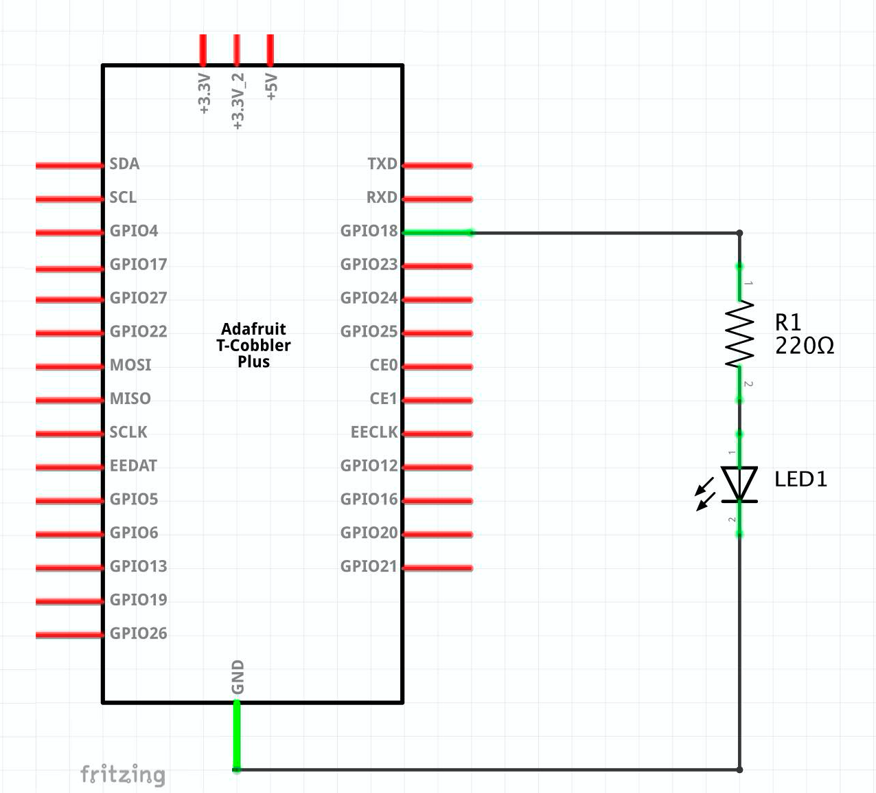
BTW, The 220 Ω resistor is needed to protect the LED. When I build this circuit, I connected the oscilloscope to see the Pulse-Width Modulation (PWM) in action and a multimeter to measure the current going through the LED.
Hardware-based PWM (RPIO)
Hardware-based PWM does not require CPU resources, and it has a more precise time control. Even if the CPU is busy, the Raspberry Pi updates the correct values at the correct time.
UPDATE Bogusław Kempny has indicated, on a comment for this article, that the Raspberry Pi only has 2 channels. Pins GPIO12 (pin 32) and GPIO18 (pin 12) share channel 0, and pins GPIO13 (pin 33) and GPIO19 (pin 35) share channel 1.
That means that we can’t drive an RGB LED because it requires three PWM signals! (one for each colour). In that case, we may want to consider using DMA-based PWM with PIGPIO
The code below uses Hardware-based PWM via the RPIO npm package.
Although this is a simple project, I have decided to write the code using two classes: LedRPIO handles the hardware, and LedLogic handles the logic. Organizing the code this way allows me to separate the usage of RPIO and swap this part for another class that uses PIGPIO in the following article. The logic is quite simple. An infinite loop varies the duty cycle by 20%, either increasing or decreasing the percentage. Each iteration of the loop occurs every second.
There are some numbers that we need to discuss:
As shown on the oscilloscope in the video above, the PWM frequency (duty cycle) is 6.75 kHz or a period of 148 microseconds. NOTE: This frequency is related to the duty cycle and does not indicate how often the data changes. In our example, the data changes every second, but this is not the frequency we discuss here.
This formula helps calculate the PWM frequency: CLOCK / (range \* ClockDivider) taking into consideration these values:
- CLOCK: The Raspberry Pi 4B has a PWM input clock that runs at 54 MHz.
- ClockDivider: Must be a power of two, for example, 2, 4, 8, 16, 32, 64, 128, and so on up to a maximum of 1024.
With a range of 1000 and a ClockDivider equals 8, we get a PWM frequency of 6.75 kHz.
Let’s take a look at other parts of this code.
1Import the RPIO library2Import the pins library. See the article GPIO Pins to understand why this is required.4-25This class isolates the hardware implementation using RPIO from the part that controls the duty cycle percentage.27-75We are controlling the duty cycle percentage.-
77-78This is just the invocation of the main code. 5The duty cycle is divided into 1000 pieces, so when we increase 20%, we are increasing by 200 points.6ClockDivider helps define the frequency or period of the duty cycle.7We are using GPIO18, but we need the physical number of the pin. We use GPIO Pins to - calculate the value.11Opens the GPIO18 pin for PWM functionality.12Sets the clock divider for the duty cycle.13Sets the range of values. In our case, we are using values from 0 to 1000 (range passed as a parameter to the constructor)16-19Receives the percentage, a value greater than 0 and less than or equals 1, indicating the duty cycle percentage.18Writes the value when it changes. In our case, this happens once per second, and it’s not related to the duty cycle frequency.-
22Close the application by resetting the pin and turning the LED off at the end of the application. 36We are going to update the percentages once per second (1000 ms).39Instantiate the class that handles the hardware.41-51Detect and handle the events when the Node.js process terminates54-63Update values when we reach the extremes65-68If the data is within the correct range, call the hardware (67) to update the LED.71-73The infinite loop
Support me with a small contribution by Paypal or, if you prefer, buy me a coffee.
Please leave a comment
Comments are powered by Utterances. A GitHub account is required to comment. Comments are moderated. Be respectful. No swearing or inflammatory language. No spam.
I reserve the right to delete any inappropriate comments. All comments for all pages can be viewed and searched online here.
Opinions expressed in this blog are solely my own and do not express the views or opinions of my employer, wife, son, friends, boss, or anybody else! 😀
To edit or delete your comment: