
Analog To Digital Conversion (I2C) with RPIO
How can the Raspberry Pi, being an all-digital device, read an analog signal? Use an Analog-to-Digital Converter (ADC). This article discusses why we need those converters, and we focus on I2C ADCs.
In the last couple of articles, we discussed Pulse-Width Modulation (PWM), which simulates an analog signal required to dim an LED using a digital output from the Raspberry Pi. But we were not genuinely converting a digital signal to an analog one! We were only producing a high or low value (on/off, 1/0, true/false) for a predefined amount of time (duty cycle), and the analog circuit “believed,” by averaging the values, that it was an analog signal. Today we are converting an analog signal to a digital one!
Before going into how this conversion takes place, we need to understand a couple of things.
Digital Vs. Analog Signals
An analog signal is a continuous signal that represents some physical measurement. Most signals in life (speed, length, weight, brightness, sound, voltage, current, power, resistance, and many more) are analog. For example, think about the speed of a car. A fast car can go from 0 to 60 in few seconds. It does not matter how fast the car is; the speed does not change instantaneously from 0 to 60!
A digital signal represents data as a sequence of different values at any point in time. It can only take one of a fixed number of values depending on the resolution. For example if we have a signal with an 8 bit resolution, then we could obtain 28 (256) values ranging from 0x00 (00000000) to 0xFF (11111111). More importantly, those values can change instantaneously!
Analog-to-Digital Conversion
Computers, like the Raspberry Pi, work with digital signals. If you want to build a system that monitors an analog voltage, you need to use an Analog-to-Digital Converter. The ADC converts an analog signal (voltage or current) into a digital number representing the magnitude of the measured value.
By the way, a digital-to-analog converter (DAC) performs the reverse function, but we are not discussing those in this article.
There are several factors you need to consider when selecting the correct ADC for your projects, including:
- Interfaces:
- ADC chips on the Raspberry Pi can use either I2C (Inter-Integrated-Circuit) or SPI (Serial Peripheral Interface) bus protocols.
- This article uses the board provided in the Frenove kit. The board has an ADS7830 ADC chip which uses an I2C protocol.
- SPI is faster than I2C, but it limits the number of devices the bus can accept. For the Raspberry Pi, the limit is 2 devices.
- I2C is slower than SPI, but you can connect many more devices (slaves) to the I2C master device as long as the slave addresses don’t conflict.
- Number of channels:
- The number of inputs you can connect to the ADC boards.
- The ADS7830 ADC chip has 8 channels.
- Sensitivity
- Measured by its bit rate.
- A higher bit rate means that the chip has a higher resolution for measuring the input voltage, but this comes at the expense of the speed of the readings.
- The ADS7830 ADC chip has an 8-bit resolution, which means it can have 28 (256) values from 0x00 to 0xFF.
- Sample Rate
- The speed at which the ADC chip can sample and report the input values.
- The ADS7830 ADC chip has a sampling rate of 70kHz.
The information for the ADS7830 ADC comes from this datasheet.
Project
We are going to build this simple circuit.
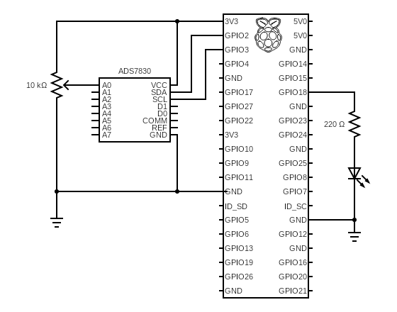
The potentiometer is going to work as a voltage divider. As we change the resistance value, the voltage detected on pin A0 of the ADS7830 ADC chip changes. The chip converts the voltages to values from 0 (representing 0 volts) to 255 (representing 3.3 volts), and the Raspberry Pi receives this value on the SDA (GPIO2) pin. Our code takes that value, displays it on the console and sends it to the class that controls the LED, which we discussed in this article Hardware-based PWM with RPIO.
Voltage Divider
Before moving to the code, we need to understand what we are testing
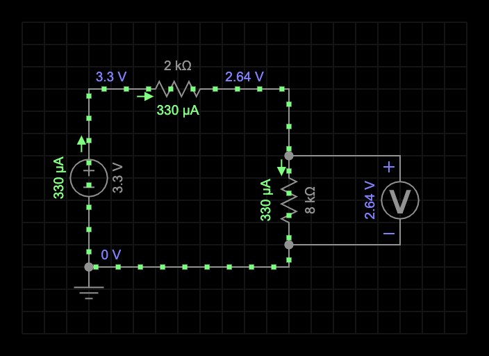
In a series circuit, like the one above, the current is related to the voltage and the total resistance (Ohm’s law). We can calculate the different values with the help of a very well-known triangle.

Because this circuit is a series circuit, the total resistance in this circuit is the addition of the two individual resistors (2KΩ + 8KΩ = 10KΩ). We calculate the current by dividing the voltage by the total resistance (3.3 volts / 10KΩ = 330μA). If we keep the total resistance fixed (10KΩ), we can change the values for the resistors (1+9, 2+8, 3+7, or any other value), and the current is going to be the same (330μA).
We are connecting a voltmeter across the second resistor to measure the voltage drop across it. Because the current (330μA) and the value for the second resistor (8KΩ) are known, we can find out what is the value of the voltage dropped across the resistor by multiplying those two values (330μA * 8KΩ = 2.64 volts).
We use a 10KΩ potentiometer (variable resistor), which allows us to change the individual resistors’ values but keep the total resistor fixed. As you can see in the video below, the voltage dropped changes. In the project we are building, we are going to measure the actual value.
In our project, we are using a potentiometer to change the resistance manually. You could use a thermistor (to find the temperature) or a photoresistor (to find the brightness), or any other components which provide a different resistance under different situations.
Configure Raspberry Pi
First, we have to configure the Raspberry Pi to enable the I2C protocol.
- Type
sudo raspi configon the terminal window. - Select
Interfacing Options. - Select
I2C. - Answer
Yeswhen asked to enable I2C. - Close the configuration tool
- Execute this command:
i2cdetect -y 1
You should see a table like this:
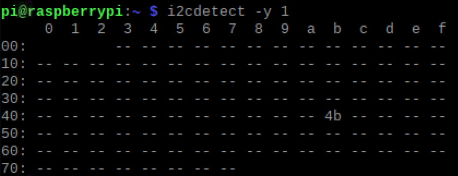
That is great, I2C is working, and we know the address that our ADC is going to use (0x4b).
Code
Below is the code for the project. Note we are using RPIO, on a future article I will rebuild this project using PIGPIO.
1Import the RPIO library2Import the pins library. See the article GPIO Pins to understand why this is required.4-31This is the class that we created to use the ADC chip. I have decided to postpone the explanation of this code to the bottom of the article because although the code is not complex, selecting the values for the constants is confusing.33-56This class is the same we had discussed in the Hardware-based PWM with RPIO article. The only difference is on lines52-54where we only want to close RPIO if this is the last usage.58-88This is the main class for our project. It’s responsible for reading the value from the ADS7830 ADC chip and providing that value to the LED so that it can be dimmed.-
90-91Create an instance of the main class and execute the code. 63Instantiate the ADS7830 class to control the inputs on the ADC chip via the I2C protocol.64Instantiate the LedRPIO class to dim the LED. Please view the Hardware-based PWM with RPIO article for more information.66-77Controls the graceful termination of the program by shutting down the ADS7830 and the LED when exiting.-
74-75Invokes the shutting down of each component, and for the last one, it sends a “true” value to theisLastparameter. 81-87Main logic for the project. Reads the value from the ADC and writes the value to the screen and the LED using a 20-millisecond timer.83Reads the value.84Updates the LED. Notice that although we measure a voltage (an analog signal from 0 volts to 3.3 volts), the ADC chip provides a digital value between 0 and 255 corresponding to the voltage read.85Outputs the value read to the screen.
ADS7830
Let’s talk about the elephant in the room: The ADC chip code!
The values for the code are only helpful if you have the same chip I have, but I want to explain where I got my values so that you can use the same code with other chips.
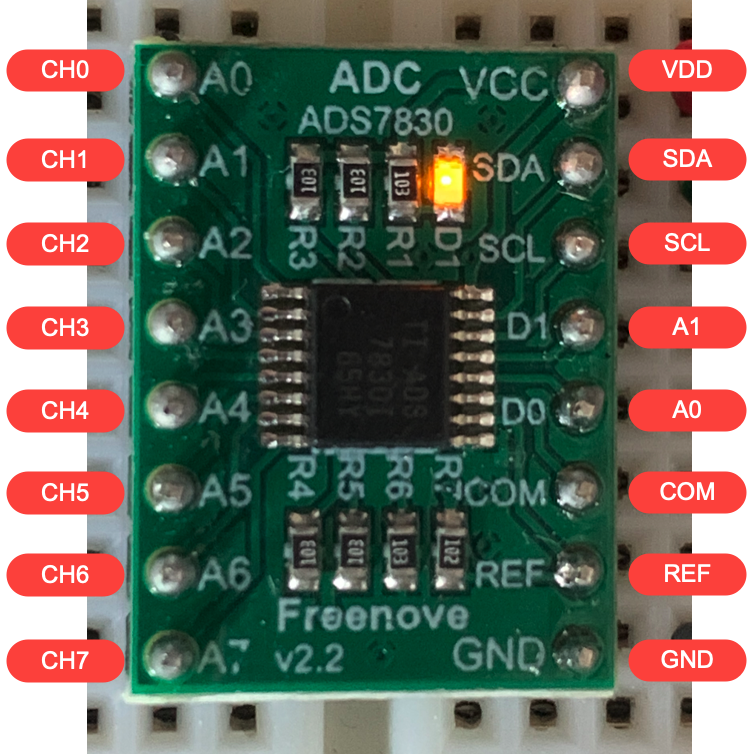
My chip (actually a board) came in the Freenove Ultimate Starter Kit for Raspberry Pi 4 kit I purchased at the beginning of my journey on this fascinating world. It came with tons of cool stuff, including this little board to do ADC conversions. Freenove mounted an ADS7830 ADC chip from Texas Instruments on a board and added some resistors… They converted this surface mount chip into something you can use on your protoboard. But for some reason, when they labelled the pins on the board, they did not use the manufacturer labels, and reading the datasheet can be a bit confusing. I have added, to the image above, the actual labels found in the datasheet.
Address
5The ADDRESS constant is how we are identifying the actual chip in the I2C bus.
For the following explanation, please bear that the board has some pull-up resistors connected to pins A0 (D0) and A1 (D1) on the right side of the board. Do not confuse these labels with CH0 (A0) and CH1 (A1) which are located on the left side of the board.
Remember, the I2C protocol allows you to have many different slaves on the bus as long as they do not have the same address. The address is “burned” into the hardware, but it can be slightly changed. Looking at the ADS7830 ADC chip datasheet, we see this:
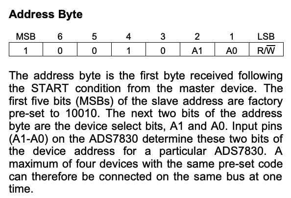
The Least significant bit (LSB) of the address byte (8 bits) indicates the operation performed. If we set the (R/W) bit to 1 then we are reading, setting it to 0 indicates we are writing to the device. So the address is only made of 7 bits, but the first 5 are factory pre-set to 10010. Remember pins A0 (D0) and A1 (D1) on the right side of the board. This table shows the possible values we have:
| Factory pre-set | A1 (D1) | A0 (D0) | Binary | Hex |
|---|---|---|---|---|
| 10010 | 0 | 0 | 1001000 | 0x48 |
| 10010 | 0 | 1 | 1001001 | 0x49 |
| 10010 | 1 | 0 | 1001010 | 0x4a |
| 10010 | 1 | 1 | 1001011 | 0x4b |
You can validate these values by requesting the information from the Raspberry Pi by executing this command: i2cdetect -y 1. As shown in the image above. Remember the board has some pull-up resistors connected to pins A0 (D0) and A1 (D1) on the right side of the board.
Channels
6The CHANNELS is a list of constants that indicate which pin we want to do the ADC conversion from.
To understand where these values are coming from, we need to go back to the ADS7830 ADC chip datasheet and look at the Command Byte
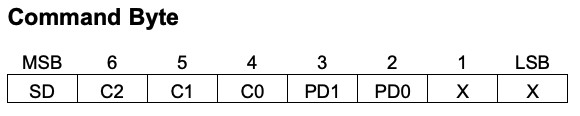
- SD: Would you like to Single-Ended or Differential Inputs?
A typical DAC gives you a choice of single-ended or differential analog input channels. Single-ended Inputs measure the voltage between the input signal and analog ground, and therefore, they require only one physical connection per input. Differential Inputs measure the voltage difference between two distinct input signals.
We are doing single-ended measurements, so we are setting this bit to 1.
- C2, C1, C0: These bits determine which pin (CH0 ~ CH7) you want to convert the analog signal to digital.
If we have three bits (C2, C1, C0), it would seem logical that you would use the binary representation to reference them (000 for CH0, 001 for CH1, 010 for CH2, 011 for CH3, and so on). But don’t let this fool you. It’s not quite so simple.
So how to know which pins (C0 to C2) for each channel? Great question! I am glad you asked. Let’s take a look at this table from the ADS7830 ADC chip datasheet.
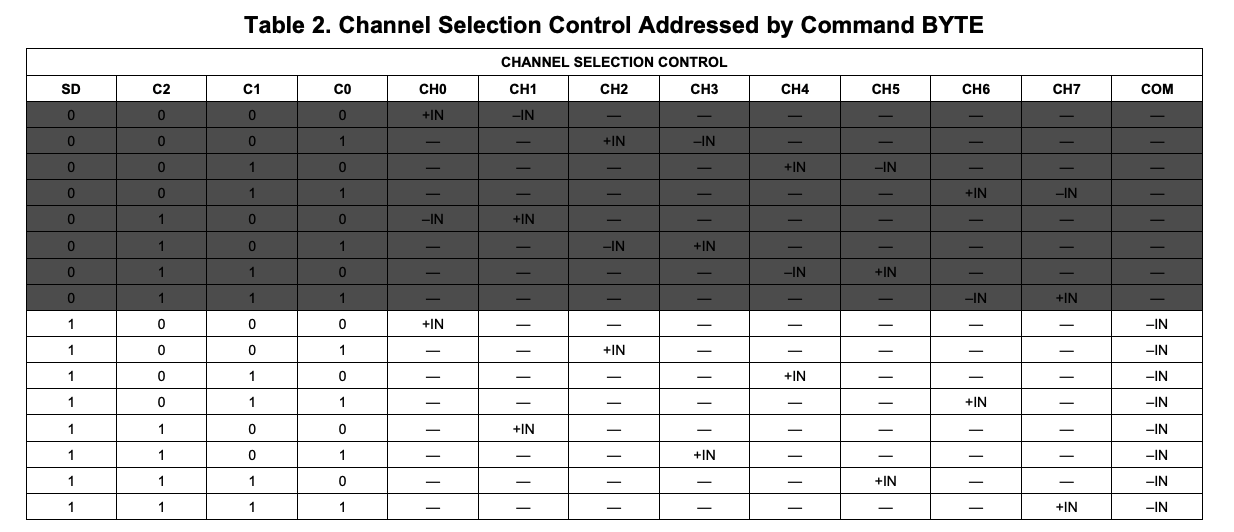
I have purposely grayed out the first half of this table because we are not using Differential Inputs, so we only care about the values with 1 in the SD bit.
Let me be honest, I have been trying to figure out why they came out with this “random” order, but it does not make sense to me at all. We have to trust the documentation and use the values they want. Since we want to convert the value from CH0, we need to use a 000 for these three bits.
- PD1, PD0: Power-Down bits.
Use this table to decide on the values You set these values according to this table:
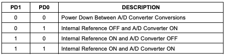
If you are concerned about power consumption, let’s say running from batteries, you could turn off the device between each value read by setting P0 and P1 both to zero. In our case, we want the convertor to keep running between readings, so we choose a 1 for PD0. But what about the “Internal Reference”? Do we want that off or on? Well, there is another section of the ADS7830 ADC chip datasheet that says:
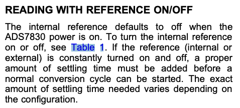
The default behaviour is to have the Internal Reference OFF. Although you could turn on the Internal reference, our code would need to worry about the time it takes for the value to settle. Or maybe, just read several values in sequence until they do not change and report that value. We do not need that level of complexity, so we are keeping the Internal Reference off. We are using a 0 in PD1 and a 1 in PD0.
- Last 2 bits: The value here is marked with an X, meaning we do not care. So let’s use a 0 for those values.
After we have gone through all these details, we are ready to make up the command byte. Let’s summarize everything we have discussed in this table:
| Channel | SD | C2 | C1 | C0 | PD1 | PD0 | X | X | Binary | Hex |
|---|---|---|---|---|---|---|---|---|---|---|
| CH0 | 1 | 0 | 0 | 0 | 0 | 1 | 0 | 0 | 10000100 | 0x84 |
| CH1 | 1 | 1 | 0 | 0 | 0 | 1 | 0 | 0 | 11000100 | 0xC4 |
| CH2 | 1 | 0 | 0 | 1 | 0 | 1 | 0 | 0 | 10010100 | 0x94 |
| CH3 | 1 | 1 | 0 | 1 | 0 | 1 | 0 | 0 | 11010100 | 0xD4 |
| CH4 | 1 | 0 | 1 | 0 | 0 | 1 | 0 | 0 | 10100100 | 0xA4 |
| CH5 | 1 | 1 | 1 | 0 | 0 | 1 | 0 | 0 | 11100100 | 0xE4 |
| CH6 | 1 | 0 | 1 | 1 | 0 | 1 | 0 | 0 | 10110100 | 0xB4 |
| CH7 | 1 | 1 | 1 | 1 | 0 | 1 | 0 | 0 | 11110100 | 0xF4 |
The rest of the code ;-)
5The ADDRESS where we can find the I2C chip (see above to understand how we got to this value)6The CHANNELS is an array of values, one for each channel that could be converted (see above to understand how we got to this value)8-11The constructor which initializes this class.9We must initialize withclose_on_exit: falseto allow for terminate the application gracefully.10This initializes I2C protocol and assigns pins 3 and 5 for I2C.13-23This method reads the values from the chip.-
25-29Terminates the usage of the I2C protocol 14Sets the address to 0x4b so that we can talk to the ADS7830 chip.15Specifies which mode we want to use to communicate to the ADS7830 chip.- The I2C protocol supports four clock speeds
- Standard-mode (100 Kbit/s)
- Fast-mode (400 Kbit/s)
- Fast-mode Plus (1 Mbit/s)
- High-speed (3.4 Mbit/s)
- The ADS7830 chip supports three I2C modes
- Standard (100 KHz)
- Fast (400 KHz)
- High-Speed (3.4 MHz)
- Here we are selecting the standard mode (100 KHz).
- The I2C protocol supports four clock speeds
17Node.js documentation explains that this function allocates a new Buffer using an array of bytes up to 255 characters long. The value we are putting here is the command byte we discussed earlier. Note that this expects an array of bytes! That’s why we have to put the value inside square brackets.18Node.js documentation explains that this function allocates a new Buffer of size (defined by the parameter) bytes. If fill is undefined, which in our case it is, Node.js fills the buffer with zeros. But this does not matter because we are using that array to get the digital conversion, overriding the value.20We are writing to the I2C bus the buffer that contains the value of 0x84, which is the command byte to request the ADS7830 to convert the analog value on channel 0.21We are reading from the I2C bus into the one-byte buffer.22We return the first byte out of the buffer, which is the value that ADS7830 converted for us.
Additional Reference
- I2C-bus specification and user manual
- Raspberry Pi SPI and I2C Tutorial
- Difference between I2C and SPI ( I2C vs SPI ), you should know.
- Analog to Digital Converter (Inputs)
- Top 12 ways to achieve low power using the features of an integrated ADC
Support me with a small contribution by Paypal or, if you prefer, buy me a coffee.
Please leave a comment
Comments are powered by Utterances. A GitHub account is required to comment. Comments are moderated. Be respectful. No swearing or inflammatory language. No spam.
I reserve the right to delete any inappropriate comments. All comments for all pages can be viewed and searched online here.
Opinions expressed in this blog are solely my own and do not express the views or opinions of my employer, wife, son, friends, boss, or anybody else! 😀
To edit or delete your comment: