
DMA-based PWM with PIGPIO
This project builds a simple circuit that uses DMA-based Pulse-Width Modulation (PWM) with PIGPIO.
Pulse-Width Modulation (PWM) series of articles:
- Read Pulse-Width Modulation (PWM) - Theory to understand the theory behind
- Build a simple circuit with RPIO using Hardware-based PWM with RPIO
- Build a simple circuit using PIGPIO using DMA-based PWM with PIGPIO
In the previous article (Pulse-Width Modulation (PWM) - Theory), we reviewed why PWM works. Let’s now take a look at how we can get PWM working on Raspberry Pi using JavaScript. The project described here today uses DMA-based PWM via the PIGPIO library.
How does the project work?
The project is the same we discussed in the Hardware-based PWM with RPIO article, so if you have not read that one, maybe it’s a good idea to do so now.
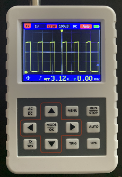
One notable difference with the previous project is the PWM frequency (duty cycle). As shown on the oscilloscope above, the frequency is 8.0 kHz or a period of 125 microseconds. NOTE: This frequency is related to the duty cycle and does not indicate how often the data changes. In our example, the data changes every second, but this is not the frequency we discuss here.
DMA-based PWM (PIGPIO)
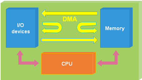
DMA-based PWM is the best of both worlds. Because it’s based the DMA (Direct Memory Access) controller, which is part of the Raspberry Pi’s chip (Broadcom), it has the efficiency of hardware-based PWM but you can use any GPIO pin. You are not limited to only 2 channels, you have 10 channels!
The DMA (Direct Memory Access) controller can’t run code (like the main chip does), but it can copy memory across peripherals by itself without consuming the central processor’s time. The DMA controller has 10 different channels which can copy memory, and it runs independently of the CPU. Providing PWM via DMA frees the CPU, allowing low processor usage to drive DC motors, servos, LEDs, or any other analog device using the GPIO pins. Raspberry Pi allows you to control a total of 10 individual channels, not just 2 like hardware-based PWM.
The code below uses DMA-based PWM via the PIGPIO npm package.
Although this is a simple project, I have decided to write the code using two classes: LedPIGPIO handles the hardware, and LedLogic handles the logic. As discussed here (Hardware-based PWM with RPIO), this organizing allowed me to separate the hardware and swap the old RPIO for the new PIGPIO library. The logic is quite simple. An infinite loop varies the duty cycle by 20%, either increasing or decreasing the percentage. Each iteration of the loop occurs every second.
PIGPIO has really good documentation Gpio class and Configuration. I wrote the code for this project extracting much of the information from those pages, but let me explain the important parts and the numbers I used as we go through the code.
I am only explaining the first 30 lines because the rest of the code is identical to the one discussed on the Hardware-based PWM with RPIO article. Please read that article too.
1Import the PIGPIO library.2Define a constant Gpio to reference the Gpio class in the Pigpio library.3Import the pins library. See the article GPIO Pins to understand why this is required.5-29This class was swapped from the previous project to use Pigpio.6Hold a reference to the LED.7-9Some good numbers that we are discussing in just a little bit.10Define the pin on the Raspberry Pi that is attached to the LED12-19The constructor initializes the DMA-based PWM using Pigpio.13Initializes the Pigpio C library. We need to initialize this because we want to close the application and turn off the LED gracefully.14Configures the clock for PWM and a sample rate of 5 μs. The sample rate can only be one of these values: 1, 2, 4, 5, 8, or 10. Read more here15We are initializing the GPIO class for the pin where we have the LED connected to be an output pin.16Selects the duty cycle range to be used for the GPIO. Values go from 25 to 40,000. Read more here17Sets the frequency in hertz to be used for the GPIO. The selectable frequencies depend upon the sample rate (in our case, it’s 5 μs) using the table found here18Initialize the LED by turning it off.22Changes the duty cycle value, and the brightness of the LED changes as a result.26Turn the LED off before shutting down.
The rest of the code is the same as the code in this other article Hardware-based PWM with RPIO
Support me with a small contribution by Paypal or, if you prefer, buy me a coffee.
Please leave a comment
Comments are powered by Utterances. A GitHub account is required to comment. Comments are moderated. Be respectful. No swearing or inflammatory language. No spam.
I reserve the right to delete any inappropriate comments. All comments for all pages can be viewed and searched online here.
Opinions expressed in this blog are solely my own and do not express the views or opinions of my employer, wife, son, friends, boss, or anybody else! 😀
To edit or delete your comment: